
The C63 AMG Build

From This in October 2024

To This In March 2025


Welcome to the LMS #02 car build.
The build process will cover the entire process from the time we stripped the donor car to the first test day at Morgan Park.
This process all started in October 2024 when we took delivery of the shell from the team at AMG Spares on the gold coast, who specialise in the the supply of AMG parts from salvaged vehicles that are statutory write-off as we as repairable write-off vehicles.
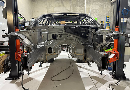
This W204 C63 AMG was destend for the scrap yard, was straight as a die with zero damage but shed been a water damage writ off she was perfect for out build. It takes around 48 hours to trip a W204 down to the shell to have it ready for a roll cage to be installed. We removed everything leaving only the front and rear cradles in to we can roll the shell around. As you can see from the photos it was in fact stripped bare.
The only part we need to leave in is the dash as its near impossible to get that dash back in after the cage is install as the reo bar behind the dash used mounts that are mm away from the main bar so its easier to leave it in.
It also helps the fabricators when it comes to the placement of the bars for the roll cage. When it comes to the cage design we need to follow the Motorsports Australia 3rd CATEGORY – TOURING CARS as well as the SCHEDULE J – SAFETY CAGE STRUCTURES for the roll cage guidelines.
Links
The Roll Cage


The process of getting the roll cage installed takes time and its important to have a highly experienced fabricator, who's able to follow the MA SCHEDULE J – SAFETY CAGE STRUCTURES guidelines.
For this build we engaged the services of Matt Gilmore for KCK Lubricants, KCK lubricants is an Australian owned company who blends, manufactures and bottled their own engine oils, right here is QLD and are used Australia wide in all forms of motorsports.
Lucky for us, Matt is also a very skilled fabricator so the shell was shipped of and 3 weeks later the cage was in.
After some cleaning we then shipped the shell off to get a paint job.
"KCK Lubricants has been developing and refining its range of oil products since 1982, many top level motorsport teams have used and still use KCK’s products with great success in a wide variety of motorsport disciplines"
Links
- KCK Lubricants - Fabrication Facebook
- https://kcklubricants.com.au
- SCHEDULE J – SAFETY CAGE STRUCTURES
The Paint Job


The painting off the cage was next on the list so after a thorough clean and some preparation work, we shipped the shell off to get a coat of paint.
We choice a darker colour for the roll cage so it was close the shell colour and were please Justin Kahl from Prostreet Fabrications. was able to provide the service.
Justin's attention to detail was what I was looking for and that proof is in the pudding.
The process took about 4 weeks and on the 24th of December 2024 it was finished which meant I could start moving all the running gear from the OG over to the new shell.
Links
- https://www.facebook.com/prostreet.fabrication
https://https://www.facebook.com/prostreet.fabricationwww.facebook.com/prostreet.fabrication
The process of moving everything over

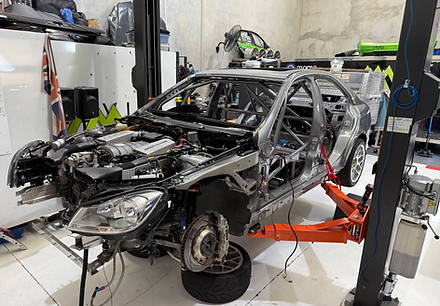
The process of moving all of the main running gear from the OG to the new shell started by removing the workshop spare front and rear cradles, that we use to move the car bodies around.
We never had any intentions of reusing any of the wiring from the OG in the new shell due the many additions, cuts and repairs over the years so I decided early on to start things like brake lines, heat shielding, lights first. The process was made a lot easer with a car of each of its own hoist. Later in the process we we hot a point were there was more in the new shell than the OG so look out for those photos.
I started on the rear end first, with some new rear lights and some heat sheilding. The new heat shielding was important the older parts had some damage missing the screw lug to connect to the bumper.

The new shell and the OG all ready to go up to a hoist.

Passenger side heat shielding and boot vent installed as well as the bumper support bracket.

On the inside of the boot I installed a neca duct to mount and fan onto to assist in removing the hot air from the boot. This was exiting the driver side boot vent.

With the bumper I then attached the new MCA Gold, custom made shocks to the rear of the car in preparation of the rear cradle being atthaced.

With the diff cooler installed, I could run the first of the -6 braided lines to the cooler.

The rear reinforcement bar is critical to protecting the car body from any rear damage that may occur in the event of rear damage.

Driver side heat shielding and boot vent installed as well as the bumper support bracket. I also installed a new exhaust mounting ruber.

Once the lights, boot lid brackets and lights were in it was ready to attach the bumper.

Before the cradle in installed, I need to install and 2x2 -6 AN bulkhead oil line connector to allow form the gearbox and diff oil cooling lines to access the boot sapce were the coolers would be.

The process of installing all of the lines for the Diff cooler, fuel lines, fuel return line as well as the 2 transmission lines took some time as we need them to have the ability to move freely and not be restricted by the rear cradle, once installed.

Rear cradle removed from the OG

With the rear cradle installed I could connect the brake lines and a wheel so we can see how that sites,

Rear cradle ready to be installed.

I could also then install that transmission and diff cooler equipment.
The cool suite venting - Chillout Systems

Before we start fitting out the interior and the engine bay its important to get the vents installed.

The air outlet hole is the location of the heater hoses access through to the heater box. The Chillout 4" round vent is perfect for that hole.

The main air inlet is taken from AC vent so I didn't have to cut the firewall to bring the air in.

The air outlet exits behind the engine heat shield in a low pressure area.
The Build and Fit Out
To start putting the engine bay together we first started with the wireing , brake lines, ABS unit and headlights.

With the wiring placed in the engine bay it was then easy to attach the core engine bay parts like the water res, Master cylinder, ECU mounting bracket as well fitting the ABS connectors that are placed in the strut tower.

It's important to install the ABS unit with the brake lines first as the wiring and brake lines to the master cylinder run around the back of the firewall.

Before the wiring harness was installed, I stripped the harness making it possible to see what wires go to what parts. It also allows you to lay the wires out in a way that make it easier to access.


Getting the headlights in....

Before we start with the engine and transmission the oil lines to the coolers needed to be ran so they can be easily installed and fixed to the body.

The transmission oil lines are wrapped in some heat shielding and fixed to the underside of the shifter.

Getting the headlights in....

The transmission oil lines do fit easily above the transmission.

When the transmission is installed the lines are then cut to length and fitted off with enough length to allow the lines to drop down to drain.

After the brake master cylinder is fitted the heat shielding is installed.

I also install and extra heat shield to prevent the Brake master cylinder from over heated.

With the engine still mounted to the cradle makes it easy to bolt in as there are only 4 bolts that fixes the cradle tot he shell.

To prevent the ABS module from being heat effected i instal and extra heat shield that is held in by the factory ABS plate.

Once the heat shielding is installed it is time to lower the shell onto the engine cradle.
With the engine in the bay the car starts to look complete. Before we move car off the hoist i need to get the transmission in and the heat shielding on.

Before the exhaust goes in the heath sheilding to protect the fuel tank and tail shaft is installed.

To protect and to keep the transmission cool, that curved heat shield is also installed to minimise the radiated heat from the hot exhaust.

I also place a small sheild on the exhaust pipe, below the drive shaft CV Boots to prevent them from failing. (yes we have had that happen)

The x-pipe holds the 3" exhaust pipes neatly apart.

This in done on both sides...

The complete under car view.....

Now that the drive train was in, we could move the car off of the hoist and onto the car stands to allow free access to the cabin.

Once the ducting was in the dash was next. The dash was easy to install through the windscreen opening.
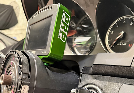
As I didn't want the dash on the steering wheel, I was able to mount the PRP M125 Motec dash mount on the cover.

Floors In with a little gap under the seat to allow access to the cables.

The next thing to go in was the Racetec Seat.

Before I started fitting the electrical components, the cooling system ducting needed to go in as we have a lot of stuff going around it.

To keep as much heat as we could out of the cabin I had a 3D printed side piece made so the Chillout System was 100% fully contained. You can see in the image above that a Chillout 275 CFM fan was installed to fill the air through the system to the exit vent.

Before I started laying cables across the floor of the car the rasiers for the floor on the the drivers side were instaled.

The next thing to go in was the Racetec Seat.


With the steering wheel installed I got to see what the new rig was going to look and feel lke.

The addition to this build was the single PWR transmission cooler out front with and triple pass radiator behind it.

The window net was fitted before we put the doors on.

Cars complete...

Off to Graphtec for the new wrap.

Graphtec getting a wrap....

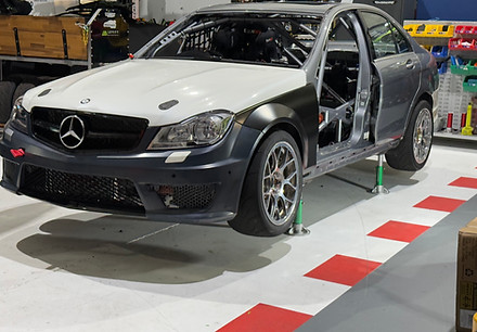
Car is back in the shop looking great.

The cabin has a lot going on...

After months of building the car, we are finally ready to going racing.

Fitting the doors on...
Bonnet, Bumper and guards are go on...

So pleased, the car looks awesome.

Off to Graphtec for the new wrap.

Wrap is on I couldn't be happier.

Tough front end.

The cabin has a lot going on...

Photo from the track day at Morgan Park.